
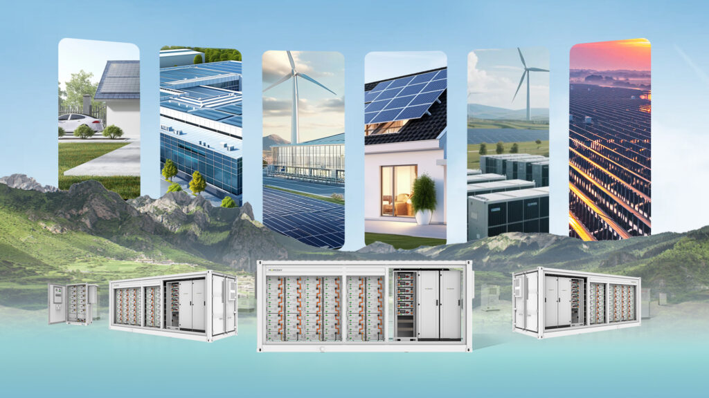
Energy storage is at the heart of the energy transition, powering homes, businesses, microgrids, and electric mobility. As capacity and deployments grow, safety moves from an engineering checkbox to a business-critical requirement. When people talk about a Battery Safety Mechanism, they’re naming more than a single device or test: it’s the layered strategy, hardware, and software that together keep cells stable, systems predictable, and users safe. This article walks through those layers in a continuous, easy-to-understand narrative — explaining why each protection matters, how manufacturers implement it in practice, and what buyers should look for when choosing or operating a system.
Table of Contents
ToggleThe multi-layered philosophy behind safety
Think of a modern energy storage cabinet as a small city. Cells are the residents; modules group into neighborhoods; the enclosure is the city wall; and a network of sensors, controllers, and emergency responders watches over everything. A reliable Battery Safety Mechanism relies on redundancy and diversity: electrical protections stop excessive currents, thermal solutions control heat, chemistry choices reduce inherent hazards, and intelligent software coordinates preventive action long before an emergency arises. No single measure is sufficient; safety is an emergent property of the entire design working together.
Cell chemistry and intrinsic safety
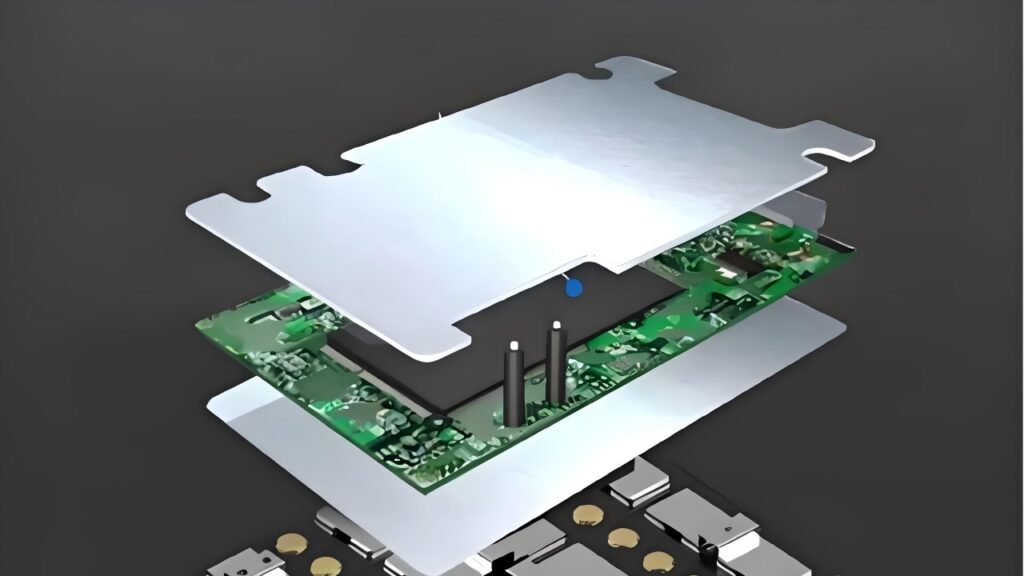
Safety starts with chemistry. Different lithium chemistries behave very differently under stress. Some chemistries release energy and heat rapidly when damaged or overcharged; others have far greater thermal stability and are inherently less likely to trigger a runaway event. Designers who prioritize longevity and safety often choose chemistries less prone to violent thermal behavior. At the cell level, the material purity, electrode coatings, and separator quality set the baseline risk: better materials and tighter manufacturing tolerances result in fewer internal shorts and greater tolerance of rough handling.
The role of the Battery Management System (BMS)
At the center of modern safety architecture sits the Battery Management System. The BMS monitors voltages, currents, temperatures, and the calculated state of charge and health, and it enforces operating limits. But to call the BMS a simple monitor underplays its role: well-engineered BMS functions actively to prevent unsafe states. For instance, it can dynamically limit charge current as the pack approaches a top-of-charge condition, adjust balancing routines to prevent a single weak cell from being overstressed, and initiate controlled shutdown sequences when anomalies appear.
Contemporary systems increasingly use predictive algorithms that recognize subtle trends — such as rising internal resistance or small but persistent cell imbalances — and act early to avoid escalation. In short, the BMS is both the brain and the first line of defense in any effective Battery Safety Mechanism.
Detecting and managing thermal risk
Heat is the enemy of battery longevity and the common pathway to severe failure. In practice, thermal control combines design choices and active systems. The pack layout aims to minimize hotspots by spacing cells intelligently, using thermally conductive materials to even out gradients, and placing temperature sensors where they reveal real behavior rather than idealized averages.
For smaller residential systems, passive convection and intelligently routed air paths can be sufficient; for larger systems, manufacturers add forced-air circulation, liquid cooling channels, or even phase-change interfaces that absorb transient heat without spiking cell temperatures. The goal of all these measures is the same: keep the operating temperature within a range that preserves SEI integrity, prevents rapid chemical reactions, and allows the protection system time to intervene if a fault begins.
Preventing propagation and managing incident response
Even with careful design and active monitoring, a failing cell can occur. The critical step is to prevent a single failing cell from triggering a neighboring cell and causing propagation. To do this, engineers use both passive and active strategies. At the module level, physical barriers and thermal insulation slow heat transfer between cell groups. Structural design often incorporates vents and pressure-relief paths that direct gases away from sensitive areas, and many systems include materials that absorb or block flame and heat.
On the active side, early detection — including smoke and gas sensors, rapid temperature rise detection, or abrupt voltage changes — triggers isolation actions such as opening contactors, disconnecting the module, and routing cooling resources to the affected region. This coordinated behavior is a crucial component of the whole Battery Safety Mechanism because it buys time and prevents a local event from becoming systemic.
Electrical protections that act instantly
Mechanical and electronic devices protect the system from excessive electrical stress. Fuses and circuit breakers physically interrupt current flow when a short or fault produces dangerously high amperage. High-voltage contactors provide reliable isolation under normal control, while specialized fast-acting devices can cut current within milliseconds during catastrophic faults. Complementing these components, ground-fault detectors and surge arrestors protect against leakage paths and transient voltage spikes caused by lightning or switching events. Together, these elements assure that, when the BMS detects a condition beyond what software alone should handle, the hardware has the capability to immediately protect the pack and downstream equipment.
Structural engineering and environmental protection
Proper enclosures are more than cosmetic: they form a critical part of the safety system. A well-designed cabinet resists water ingress, dust, and mechanical impact, yet it also ensures that if a cell vents, the released gas and heat are directed away safely. Reinforced frames and shock mounts reduce the risk that vibration or transport forces will cause internal shorts. Pressure relief features and strategically placed vents help manage an internal failure without exposing users or the environment to risk. For outdoor applications, meeting established ingress protection standards provides additional peace of mind; the enclosure must keep contaminants out while giving emergency systems the channels they need to work.
Software, connectivity, and remote oversight
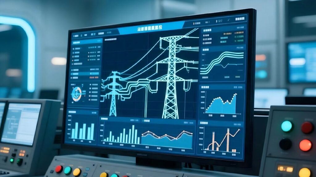
Operational safety increasingly relies on software that gathers data, analyzes trends, and issues warnings well before a problem becomes critical. Remote monitoring platforms aggregate telemetry from many systems and can detect fleet-level patterns that a single site might miss. Alerts let operators schedule maintenance, update charging profiles, or dispatch technicians proactively. Importantly, these digital layers also support firmware-level safety features: a BMS receiving updated algorithms can improve balancing efficiency, change cutoff thresholds based on field data, or implement new protection logic in response to newly discovered failure modes. These capabilities extend the lifespan and resilience of the physical protections and are part of what distinguishes a mature Battery Safety Mechanism from a basic pack.
Standards, testing, and third-party verification
Robust safety does not rest solely on internal design decisions. External testing and certification show that a product meets a set of standardized criteria under controlled, repeatable conditions. Tests for transportability, abuse tolerance, and thermal behavior, carried out by accredited bodies, provide a benchmark that customers and regulators can trust. Compliance with recognized standards gives system owners confidence that the design has been challenged against well-known failure scenarios and that the protective measures perform as claimed. In many markets, certifications are also a legal or commercial prerequisite for deployment, insurance, and grid interconnection.
Real-world failure modes and how mechanisms mitigate them
To keep the discussion practical, consider common failure pathways and how modern designs prevent them. Overvoltage conditions caused by grid instability are mitigated by coordinated action from inverters and the BMS: the system can hold the pack at a safe voltage, shed load, or disconnect until conditions normalize. Thermal incidents from high ambient temperatures are addressed through derating and active cooling. Mechanical damage, whether from shipping or site events, is reduced by packaging, shock mounts, and early electrical disconnect. Each mitigation strategy reduces the chances that a localized fault grows into a catastrophic event, and when combined they form a resilient Battery Safety Mechanism that protects assets, property, and lives.
What buyers and integrators should evaluate
Choosing a safe energy storage system requires looking beyond headline specifications. Chemistry is a starting point, but lifecycle management, design transparency, and serviceability matter as much. Buyers should ask about the logic and redundancy in the BMS, the quality and placement of thermal sensors, the presence of propagation mitigation features, and the practicalities of emergency disconnect. Equally important are the software tools: can the system provide meaningful alerts, logs, and remote access? Finally, certifications and references from comparable installations demonstrate whether the supplier’s safety claims hold up in real deployments.
Conclusion
A Battery Safety Mechanism is best understood not as a single device but as a layered, coordinated approach that spans materials science, electrical and mechanical engineering, and intelligent software. As energy storage moves from niche to mainstream, safety systems will continue to evolve, guided by lessons from field experience and advances in monitoring and materials. For users and specifiers, the right question is not whether a product claims to be “safe,” but whether its combination of chemistry, architecture, monitoring, and certification creates a demonstrably resilient, maintainable system that fits the intended use case.

Ryan Huang
Hello everyone, I’m Ryan Huang, founder of Moreday, a company specializing in solar-powered ev charging solutions and pv power transmission and distribution. Over the past 17 years, we’ve helped nearly 6000 customers in 67 countries (including farms, residential, industrial, and commercial users) solve their renewable energy and green power needs. This article aims to share more knowledge about renewable energy and solar power, bringing sustainable electricity to every household.
